COOLING SYSTEMS
HYDRONIC SYSTEM RECOMMENDATIONS FOR AIR-COOLED CHILLERS
A hydronic system is an installation that uses water (or glycol-water mixture) as the fluid to transport heat or cooling in a building or process.
-
INTRODUCTION
These recommendations have been prepared with the goal of ensuring proper hydraulic and thermal balance between the water chiller and the customer's hydronic system. They are based on more than ten years of practical experience in the design, manufacture, commissioning, and performance analysis of chilled water systems. Their purpose is to provide designers, consulting engineers, contractors, system integrators, and investors with practical guidance for selecting the optimal hydronic system configuration while avoiding common design and installation errors that may negatively affect system reliability, energy efficiency, and equipment service life.
Achieving proper hydraulic and thermal balance is a prerequisite for reliable and stable system operation, extended equipment service life, and maximum overall energy efficiency of the entire installation.
When designing a hydronic system, its configuration should be selected in accordance with the technical capabilities and control philosophy of the selected water chiller, as different chiller configurations are not equally suitable for all hydronic system layouts.
-
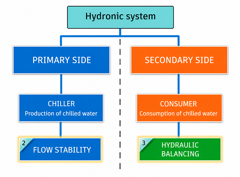
CHILLER FLOW RATE STABILITY
A stable flow rate on the primary side is one of the key prerequisites for reliable, safe, and energy-efficient operation of a water chiller and the overall hydronic system. The chiller is designed to operate at a nominal flow rate through the evaporator (plate heat exchanger), which is why it is necessary to ensure a stable flow without significant fluctuations.
Unstable or variable flow through the evaporator can disrupt the heat transfer process, thereby significantly reducing the efficiency and performance of the chiller and potentially causing damage to critical components of the unit.
Control of the flow rate
Flow regulation on the primary side is achieved by using a flow meter, a variable-speed primary circulation pump and the chiller control system.
Based on the measured flow rate, the chiller control system automatically adjusts the speed of the primary pump in order to maintain the required flow through the evaporator and ensure optimal operating conditions across the entire operating range.
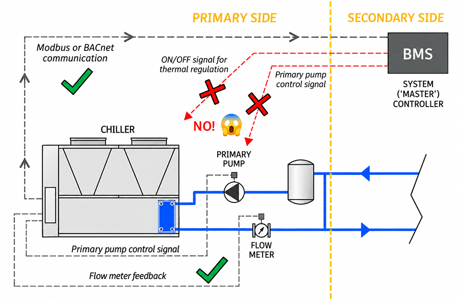
The chiller control system must have full control over the operation of the primary pump. The system controller (e.g. BMS) must not control the chiller through frequent start/stop commands for the purpose of regulating system temperature. All start-up and shutdown sequences, protection functions, and operating modes must be governed exclusively by the chiller control logic. The primary pump and/or flow meter may be installed either inside or outside the chiller housing.
-
HYDRONIC SYSTEM BALANCING
The main goal of hydraulic balancing of terminal units on consumer/secondary side, such as air handling units or fan coil units, is to ensure that each unit receives the correct flow rate under all load conditions, while preventing flow from exceeding the nominal design value. Overflow on the secondary side causes not only higher pump energy consumption but increases supply water temperature which degrades total cooling potential. We can conclude:
Total system flow must not exceed the nominal flow for which the chiller was designed. Therefore, hydraulic balancing of the system ensures proper flow distribution and prevents excessive flow.
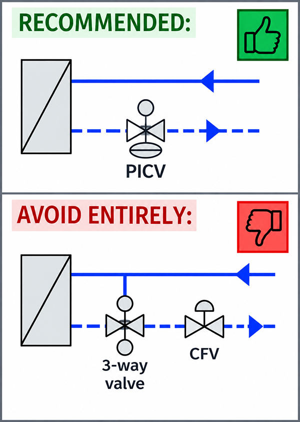
In order to achieve hydraulic balancing, it is recommended to use Pressure Independent Control Valves (PICVs) with proportional control or ON/OFF control for each terminal unit, depending on system design. (Example: Danfoss AB-QM valve, Belimo PIC valve, etc.)
PICVs are control valves with an automatic hydraulic balancing function. An in-built pressure controller keeps a constant differential pressure over the valve, ensuring automatic flow rate limitation based on a preset (nominal) value.
Properly selected and commissioned PICV valves prevent excessive flow and ensure the required flow rate through each terminal unit, regardless of changes in the system differential pressure. This maintains the hydraulic balance of the system under both full-load and part-load operating conditions.
In systems with variable flow on the secondary side, the primary (chiller) and secondary (consumer) side shall be hydraulically separated to ensure stable chiller operation independent of flow variations on the secondary side.
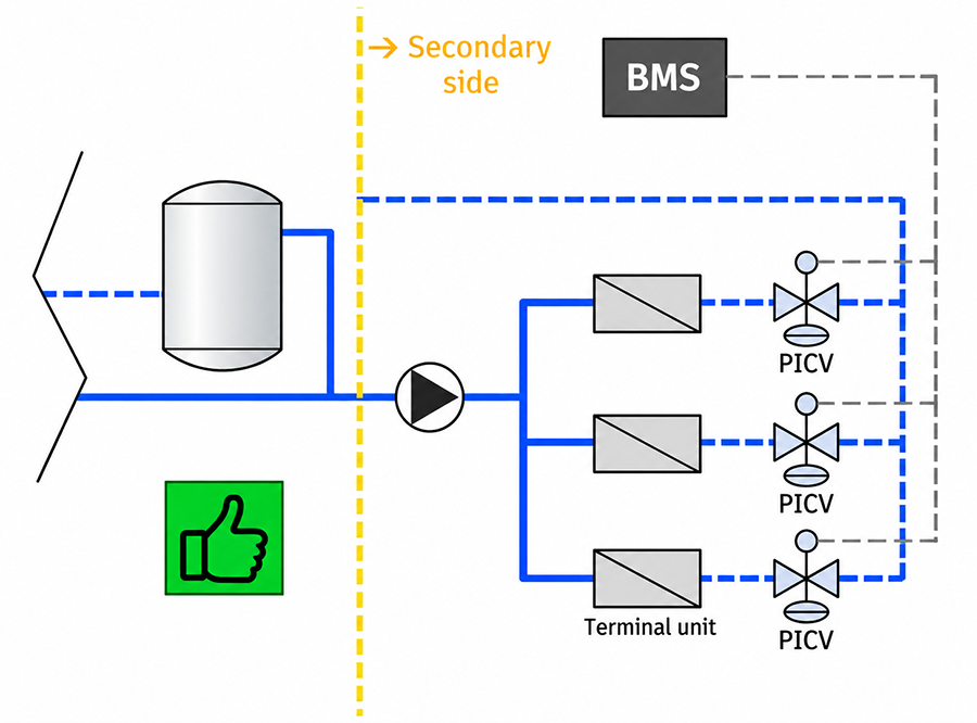
Proper setting of PICV:
- No overflow due to limited maximum flow on each terminal unit
- Right flow at all loads, regardless of pressure fluctuations
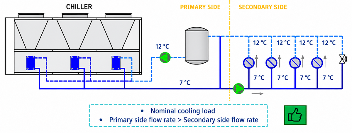
- Secondary side flow rate is always lower than primary side flow rate.
3.1 BUFFER TANK AS A STABILIZER
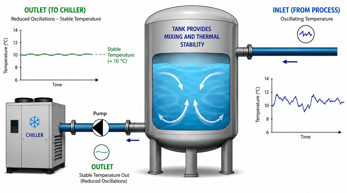
Stable return water temperature is one of the key parameters for reliable chiller operation, as the chiller control system uses it to determine the instantaneous cooling load and regulate the unit accordingly.
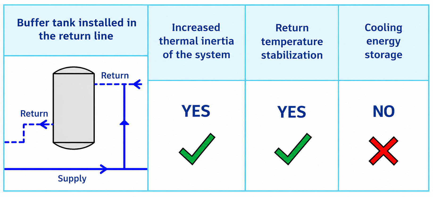
For this reason, from a technical standpoint, the buffer tank should be installed in the return water line, immediately upstream of the chiller, where it effectively absorbs return water temperature fluctuations and stabilizes system operation.
A properly sized buffer tank increases the thermal inertia of the system, reduces the impact of sudden load changes on the chiller, and prevents frequent compressor cycling.
Proper sizing of the buffer tank requires an analysis of the minimum chiller cooling capacity, the minimum possible system load, the total water/glycol volume, and the minimum allowable compressor operating time.
3.2 BUFFER TANK FOR COOLING ENERGY STORAGE?
Buffer tanks commonly installed in hydronic systems are generally too small to provide meaningful cooling energy storage due to the relatively low specific heat capacity of water. Consequently, effective cooling energy storage requires significantly larger tank volumes or latent heat storage systems, such as ice or phase change materials (PCM). The following example illustrates the limitations of a typical buffer tank volume.
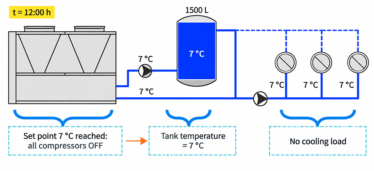
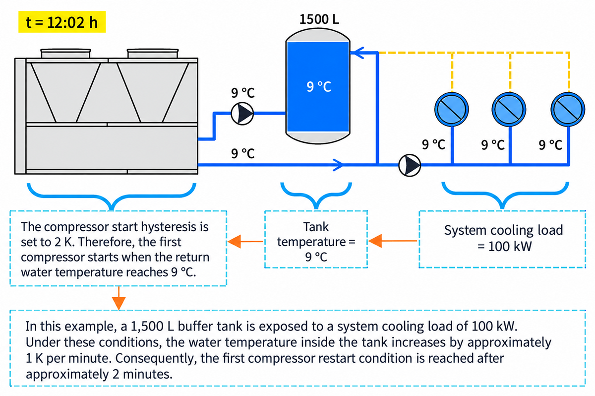
In this example, a 1,500 L buffer tank is exposed to a system cooling load of 100 kW. Under these conditions, the water temperature inside the tank increases by approximately 1 K per minute. Consequently, the first compressor restart condition is reached after approximately 2 minutes.
CONCLUSION: This buffer tank cannot serve as cooling energy storage due to its insufficient volume.


-
RECOMMENDED HYDRONIC SOLUTIONS
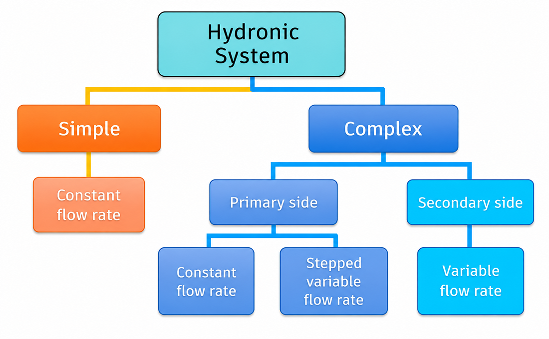
4.1 SIMPLE SYSTEM
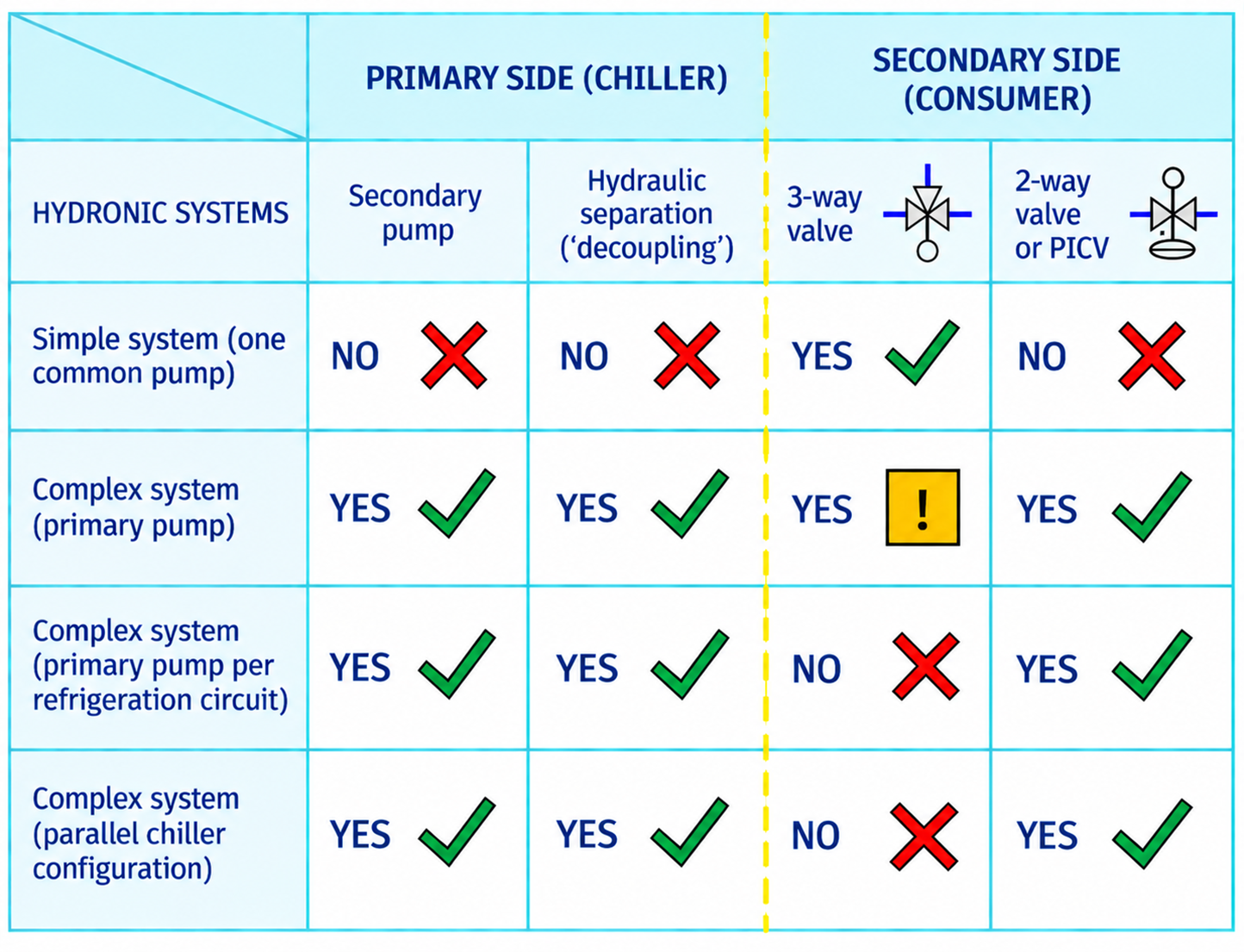
A simple system is based on the premise that the chiller and consumer side have constant, fixed flow at all times. A simple system has a single circulation pump and adequately sized buffer tank on return line.
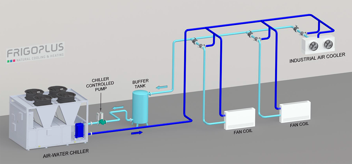
SYSTEM: CONSTANT FLOW RATE
The system circulation pump has to be controlled by the chiller in order to maintain constant flow rate.
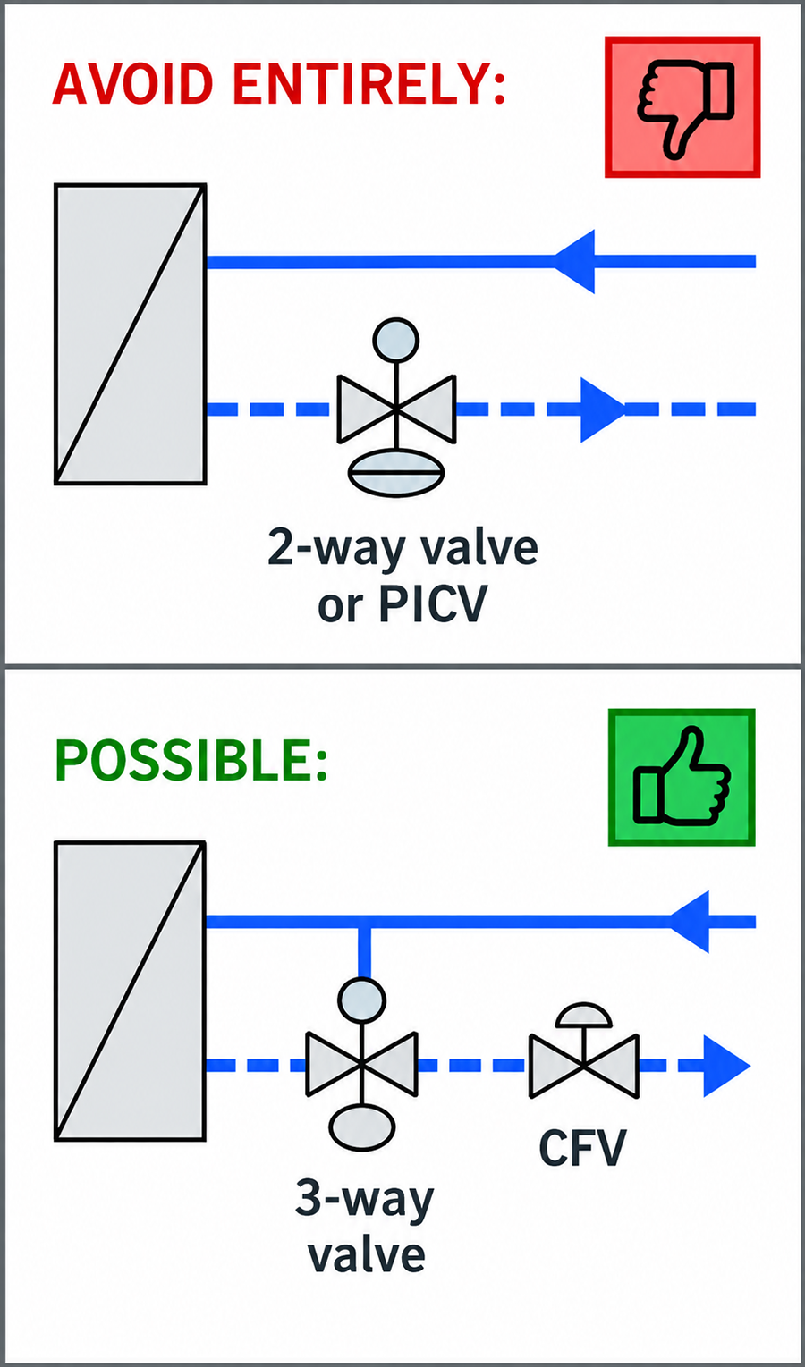
Two-way valves with ON/OFF or proportional control (with actuators) must not be used because they result in variable system flow!
However, it is possible / recommended to install:
- Constant Flow Valve (CFV) for ensuring constant flow rate in each branch, preset to nominal value of a terminal unit
- Three-way valves together with CFV for each terminal unit.
Note: Constant Flow Valves (CFV) as a control/balancing valve must always be open.
Simple system design is suitable for smaller systems with lower but stable cooling loads, consisting of relatively small number of terminal units. Recommendation: MINILINE and COMPACT series of chillers.
4.2 COMPLEX SYSTEM
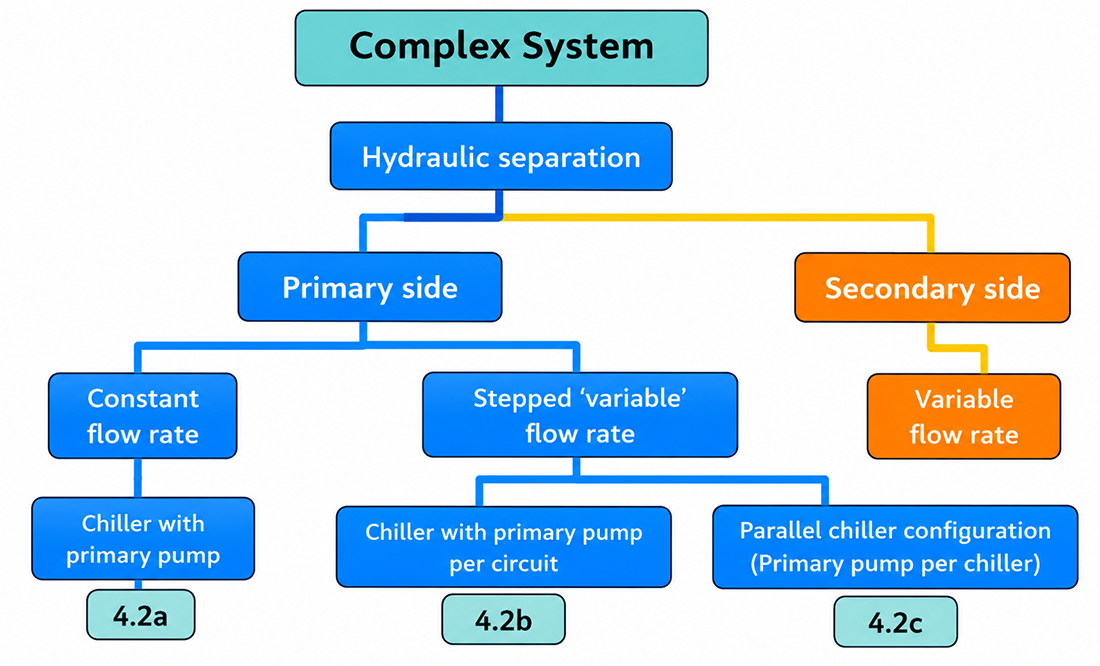
Hydraulic separation
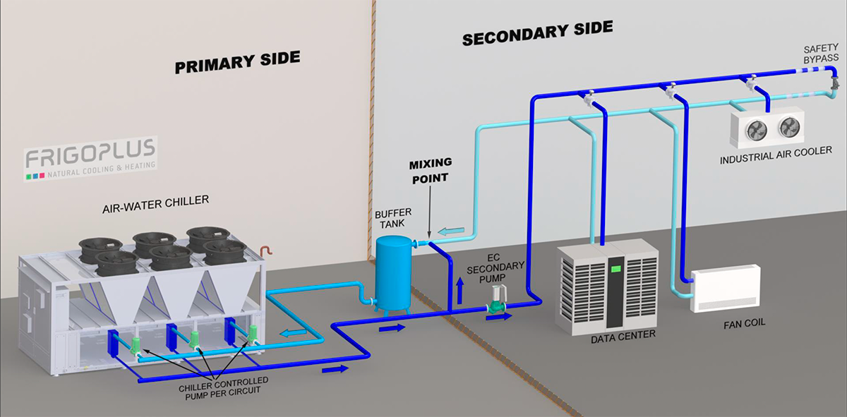
A complex system involves hydraulic separation (or ‘hydronic separation’) between the chiller side flow rate with customer side flow rate. Hydraulic separation can be achieved by connecting the supply and return line with additional piping in between them. Therefore, this defines a ‘primary’ and ‘secondary side’:
- Primary side side is the hydronic circuit (loop) which is connected directly to the plate heat exchanger of the chiller and it ensures optimal and stable flow rate required for safe chiller operation.
- Secondary side is the hydronic loop that distributes chilled coolant (water) from the chiller (primary side) to the load side of the system such as fan coil units, air handling units etc.
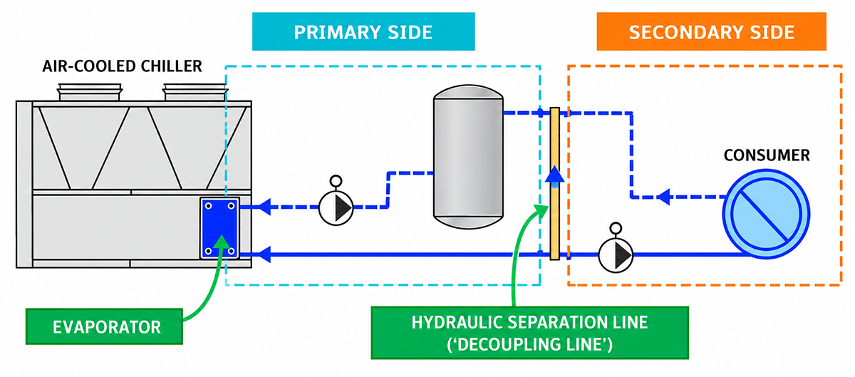
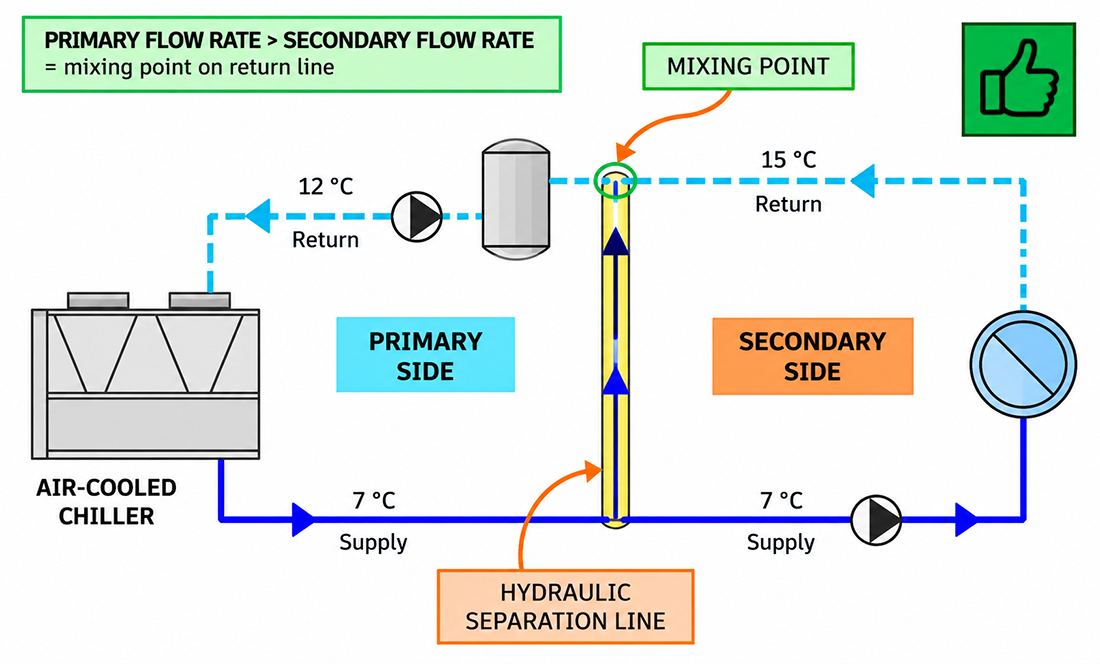
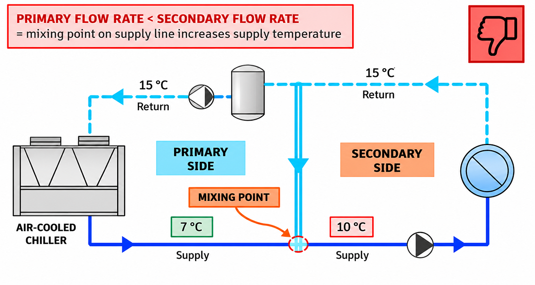
A mixing point is formed in the return pipe when the primary side flow rate is higher than the secondary side flow rate. However, if the secondary side flow rate exceeds the primary side flow rate, the mixing point shifts to the supply pipe. This results in an increase in supply temperature, which should be avoided at all times.
In complex systems, it is essential that the primary side flow rate is higher than the secondary side flow rate. – This will result in mixing point always being on return rather than on supply line.
4.2a CHILLER WITH PRIMARY PUMP
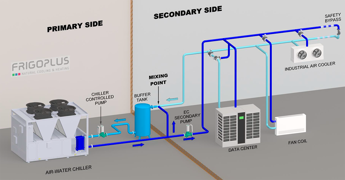
PRIMARY SIDE: CONSTANT FLOW RATE
- The primary pump has to operate constantly and be controlled by the chiller in order to control the flow rate
- Primary side total flow rate must be higher than secondary side flow rate at all times
- The hydraulic separation line compensates for the flow difference between the primary and secondary sides.
SECONDARY SIDE: VARIABLE FLOW RATE
Secondary side pump operates in constant differential pressure mode (constant Δp mode).
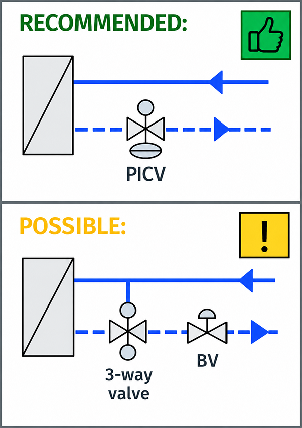
For hydraulic balancing and flow limitation, the installation of a pressure-independent control valve (PICV) on each terminal unit is recommended..
As an alternative solution, individual terminal units may be equipped with a three-way control valve in combination with a balancing valve (BV). In such cases, the flow rate through each terminal unit shall be limited to its design flow rate to prevent excessive flow on the secondary side.
4.2b CHILLER WITH PUMP PER CIRCUIT
PRIMARY SIDE: 'VARIABLE' FLOW RATE
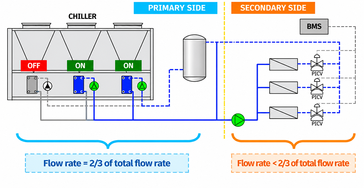
The chiller is equipped with a separate primary pump for each refrigeration circuit. Step-controlled ‘variable’ flow rate is provided through staged refrigerant circuit operation, meaning that flow rate increases in discrete steps. Each primary pump has to be controlled by the chiller.
- Primary side flow rate must be higher than the secondary side at all times
- Minimum flow rate on the primary side must be higher than the minimum flow rate on the secondary side
- The cooling capacity of each refrigeration circuit should be at least equal to the largest individual consumer load on the secondary side (e.g. a fan coil unit)
- The hydraulic separation line compensates for the flow difference between the primary and secondary sides.
SECONDARY SIDE: VARIABLE FLOW RATE
- Secondary side pump operates in constant differential pressure mode (constant Δp mode)
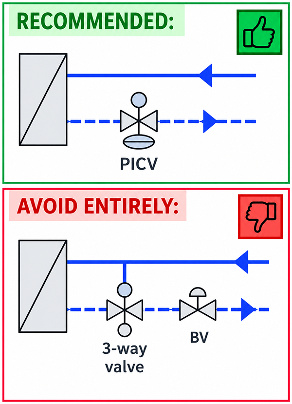
- For each terminal unit, , install a pressure independent control valve (PICV) in ON/OFF mode, , so the flow regulation matches primary side step-controlled flow rate
Three-way valves must not be used for bypass of terminal units, because that leads to overflow on the secondary side during partial load!
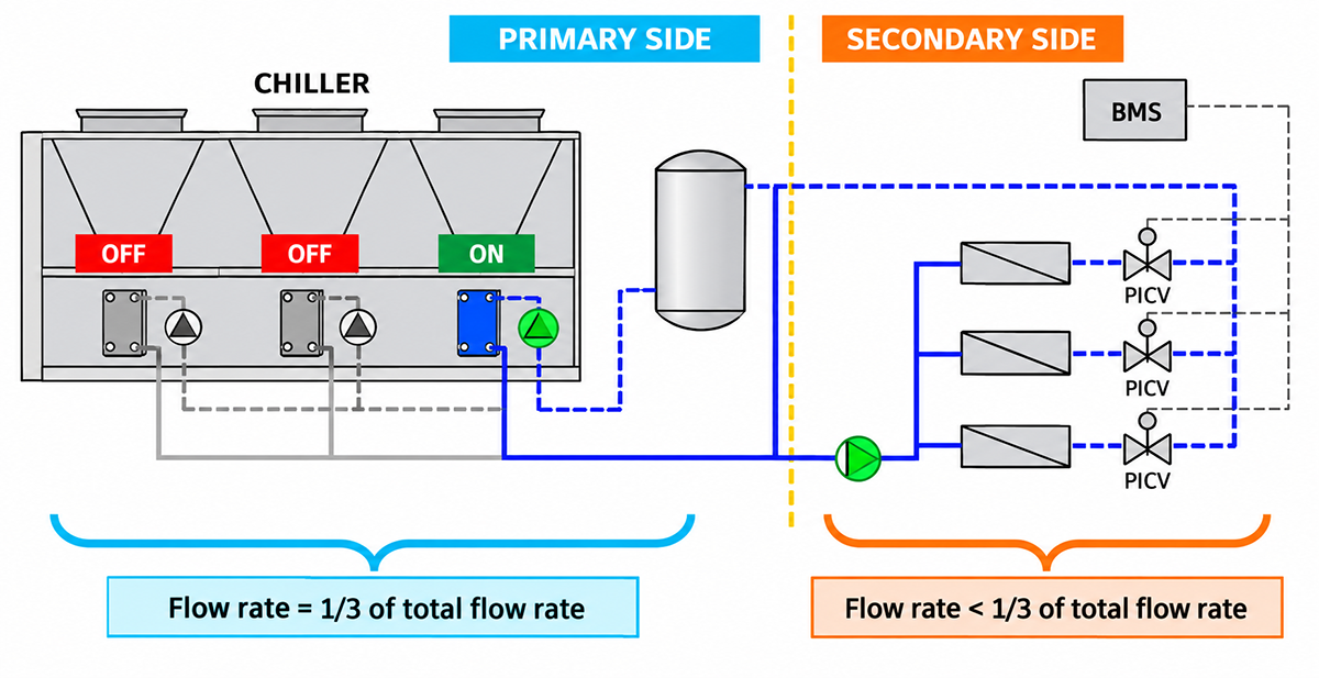
Step-controlled ‘variable’ flow rate strategy means the primary side flow changes in discrete steps (stages) based on the number of refrigeration circuits or chillers operating.
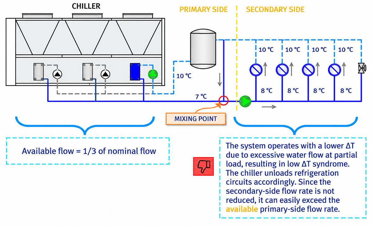
In the example shown, the chiller is equipped with a separate primary pump for each refrigeration circuit. Under part-load conditions, only one of the three refrigeration circuits is active, reducing the available primary-side flow rate to one third of the nominal flow rate. In this case, the secondary side flow rate must be less than or equal to the primary side flow rate. The same principle applies when two of the three refrigeration circuits are in operation.
4.2c PARALLEL CHILLER CONFIGURATION
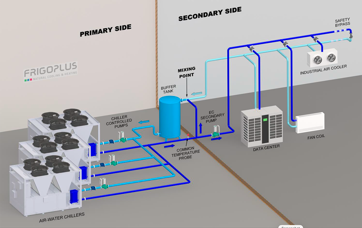
PRIMARY CIRCUIT: STEP-CONTROLLED ‘VARIABLE’ FLOW RATE
The chillers are in parallel configuration, based on a leading-following principle of operation. Therefore, step-controlled ‘variable’ flow rate is provided through staged chiller operation, meaning that flow rate increases in discrete steps.
- Total flow rate of the primary side must be higher than the secondary side at all times
- The control system of each chiller must control the operation of its dedicated primary circulation pump
- Common temperature probe must be installed on the common supply pipe
- The hydraulic separation line compensates for the flow difference between the primary and secondary sides.
SECONDARY SIDE (SYSTEM): VARIABLE FLOW RATE
- Secondary side pump operates in constant differential pressure mode (constant Δp mode)
- For each terminstall a pressure independent control valve (inal unit, PICV) in ON/OFF mode, so the flow regulation matches primary side step-controlled flow rate
Three-way valves must not be used for bypass of terminal units, because that leads to overflow on the secondary side during partial load!
-
THERMAL BALANCING OF THE SYSTEM
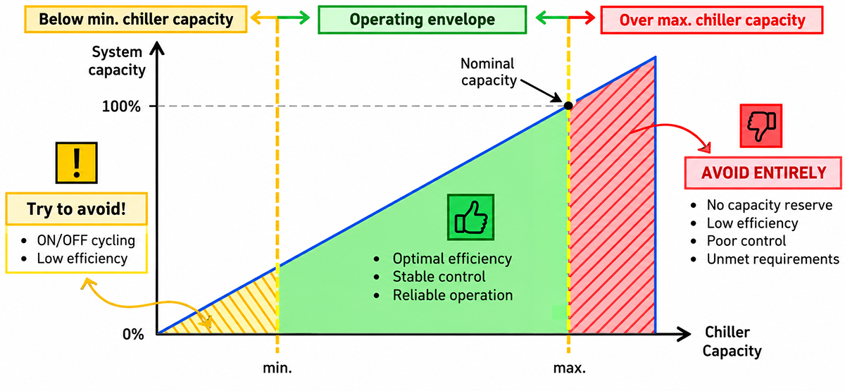
For a chiller to operate correctly with high efficiency, the system needs to be thermally balanced. . Thermal balancing is based upon keeping minimum and maximum consumer load (capacity) inside the operating envelope of the chiller.
In nominal conditions, the required cooling capacity of each terminal unit should never be higher than its design cooling capacity. → This ensures balanced thermal load distribution across the system, promotes stable operation, and prevents capacity shortfalls at individual terminal units.
The minimum system cooling load should not be lower than the minimum capacity of the chiller. → If system load falls below the chiller's minimum cooling load, frequent compressor cycling can occur, reducing operating efficiency and potentially compromising the reliability of chiller operation.
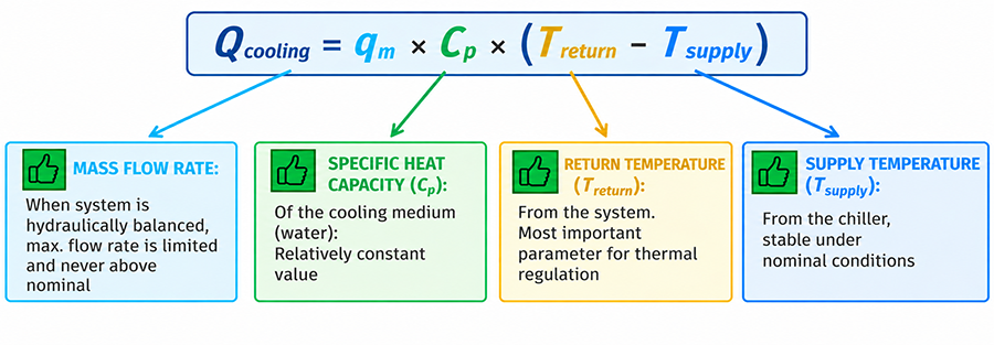
According to the standard equation for cooling capacity of the system, or simply a single terminal unit on consumer side, we can conclude that the return temperature from the system is the most important parameter of thermal balance:
5.1 MAX. TEMPERATURE DIFFERENCE (ΔT)
If the return water temperature rises above the nominal value, the system temperature difference (ΔT) also increases, assuming a constant supply water temperature. ΔT above the nominal value indicates excessive cooling demand at one or more terminal units. In this case, the total cooling load of the system may exceed the nominal cooling capacity of the chiller. This indicates a system control issue, particularly in systems where a relatively small number of terminal units account for the majority of the total cooling load.
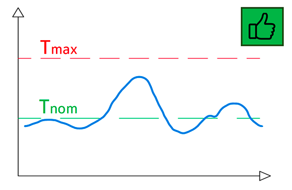
The return temperature from the terminal unit towards the chiller is in operating range. The flow control valve (e.g. PICV) provides optimal flow rate during nominal and partial load. System is hydraulically and thermally balanced.
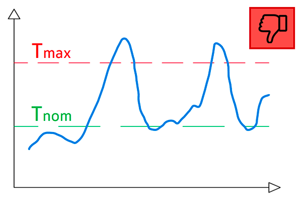
The return temperature is unstable, increasing above maximum value. Issue regarding thermal balance in the system!
It is necessary to implement measures to ensure that this does not occur. For example, the cooling load should be increased progressively to prevent abrupt operating condition changes.

An increase in the return temperature above the maximum value may occur during seasonal system start-ups following a period of inactivity, as well as in systems with highly variable thermal loads or significant peak loads.
5.2 MIN. TEMPERATURE DIFFERENCE (ΔT)
When return temperature is lower than nominal, it indicates partial cooling load conditions. Assuming constant supply temperature, lower return temperature corresponds to reduced (ΔT).
Partial load operation is expected and normal. However, if the water flow rate does not decrease in proportion to the lower cooling load, low ΔT syndrome can occur. Essentially, it is caused by a mismatch between flow rate and actual cooling load, causing hydraulic and thermal imbalance even at loads relatively close to nominal value.
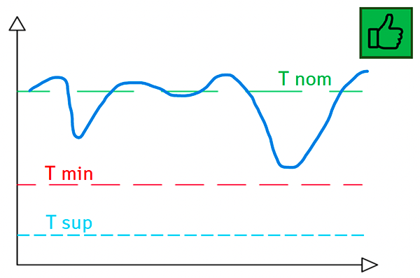
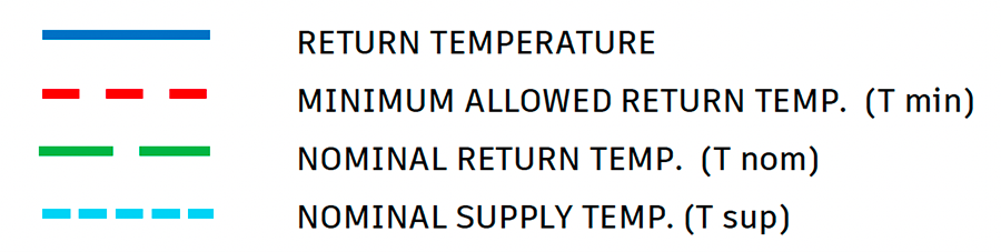
Acceptable fluctuations of return temp. from terminal unit(s)
Short-duration deviations below nominal value are acceptable provided return temperature remains above minimum (Tmin) and recovers promptly.
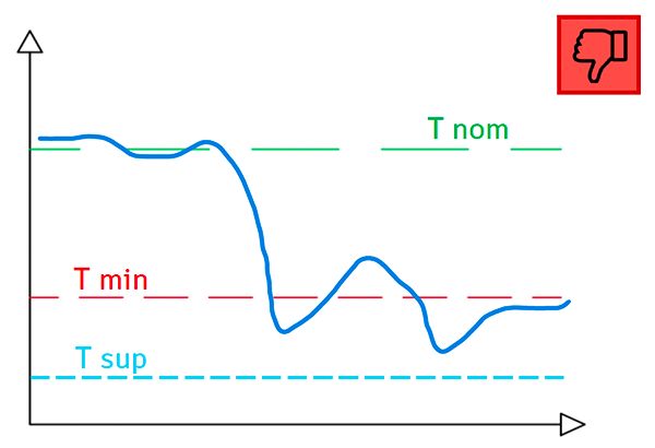
System affected with low ΔT syndrome
A lower return water temperature indicates partial cooling load. If the flow rate is not reduced accordingly, the system ΔT becomes too low (assuming constant supply water temperature), resulting in Low ΔT syndrome. Measures should be implemented to prevent this condition.
Potential cause of Low ΔT (Delta T) syndrome
Inadequate control valve selection with improper system balancing
If the system is not properly balanced, some control valves can pass too much water through terminal units (e.g. fan coils) at partial load, which causes overflow. This means there is too much flow for the actual cooling load, reducing the temperature rise (ΔT) across the terminal units and the system as a whole. During overflow caused by low ΔT, the system is unbalanced!
One of the possible solutions is to use pressure independent control valves (PICVs) with proportional control for each terminal unit. They eliminate overflow.
5.2a LOW ΔT-SYNDROME – CHILLER WITH PRIMARY PUMP
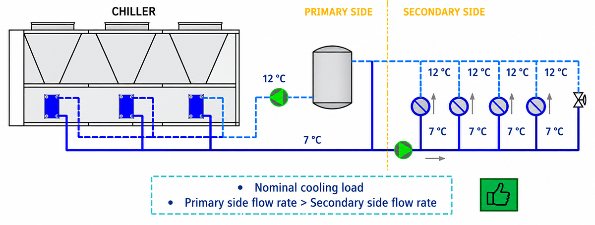
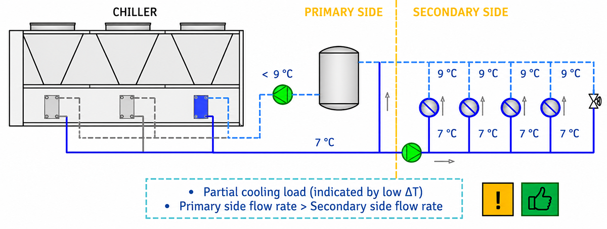
When the secondary side operates at lower than nominal ΔT, it indicates a lower cooling load to the chiller, assuming constant supply water temperature. In that case, the chiller cannot have all circuits active. When the chiller is equipped with a primary pump for all refrigerant circuits, the effects of low ΔT syndrome on chiller operation are generally tolerable and the overall chiller performance is not significantly compromised, as long as the primary flow rate exceeds the secondary flow rate.
5.2b LOW ΔT-SYNDROME – CHILLER WITH PUMP PER CIRCUIT
When the secondary side operates at lower than nominal ΔT, it indicates a lower cooling load to the chiller. In that case, the chiller cannot have all circuits active since the cooling load is low. As a result, available flow on primary side is limited, since it is regulated in discrete steps. If secondary side flow rate is not adequately reduced (or limited) during partial load, overflow causes hydraulic and thermal imbalance.
Nominal cooling load → Nominal operating conditions
Partial cooling load → ΔT below the nominal value
-
THERMAL REGULATION STRATEGIES
This chapter outlines the chiller’s thermal regulation strategies under thermally and hydraulically balanced operating conditions.
The primary goal of thermal regulation is to maintain a stable supply water/glycol temperature. Achieving this requires the system to be both hydraulically and thermally balanced.
Reminder: effective thermal regulation is possible only when stable and constant flow rate through the evaporators is ensured.
When these conditions are met, the chiller also operates within its intended operating range, as discussed in Chapter 5. Operating within this range enables efficient and reliable chiller performance, resulting in stable supply water temperature.
First, it is important to define the fundamentals of thermal regulation on which the regulation strategies are based. These fundamentals are valid for both simple and complex systems (which are described in Chapter 4 – Recommended hydronic solutions)
Set point:
- Required outlet temperature from the chiller ( = supply water temperature)
Compressor Start/Stop:
- Compressors start and stop based on chiller inlet water (glycol) temperature, which corresponds to the return temperature from the system
Inverter Regulation:
- Frequency inverters are regulated based on the chiller outlet water temperature (i.e. the set point)
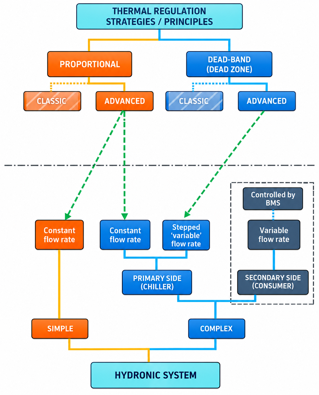
6.1 CONSTANT FLOW RATE – CHILLER WITH PRIMARY PUMP
This thermal regulation principle is valid for the following types of chiller / system configurations:
- Chiller installed in a simple hydronic system equipped with a common pump (Chapter 4.1)
- Chiller with primary pump, installed in a complex hydronic system (Chapter 4.2a)
Compressor start-up principle
The setpoint temperature + differential per compressor defines the start point of the first compressor.
Available total temperature differential ΔT ΔT is divided by the number of compressors Ncpr in the chiller (ranging from 1 to maximum 4), resulting in a differential per compressor named ΔTcpr:
ΔTcpr = (ΔT / Ncpr)
Each subsequent compressor starts when the temperature reaches:
Set point + (ΔTcpr × n)
(where n is the compressor sequence number)This ensures step-by-step activation based on increasing cooling load.
There is no starting delay regarding to inlet temperature value, but certain starting time delays exist, such as minimum compressor running time.
Compressor shut-down principle
Last compressor shuts down when the return temperature reaches setpoint.
Each preceding compressor shuts down at a threshold defined by:
Set point + (ΔTcpr × n)
(where n is the compressor sequence number)This logic ensures balanced unloading and can be visualized in the next diagram.
The following example shows a thermal regulation diagram of a chiller with 3 independent refrigerant circuits, each with one compressor (Ncpr = 3). Temperature regime is 12/6 °C, which means ΔT = 6 K and the cooling setpoint value is 6 °C.
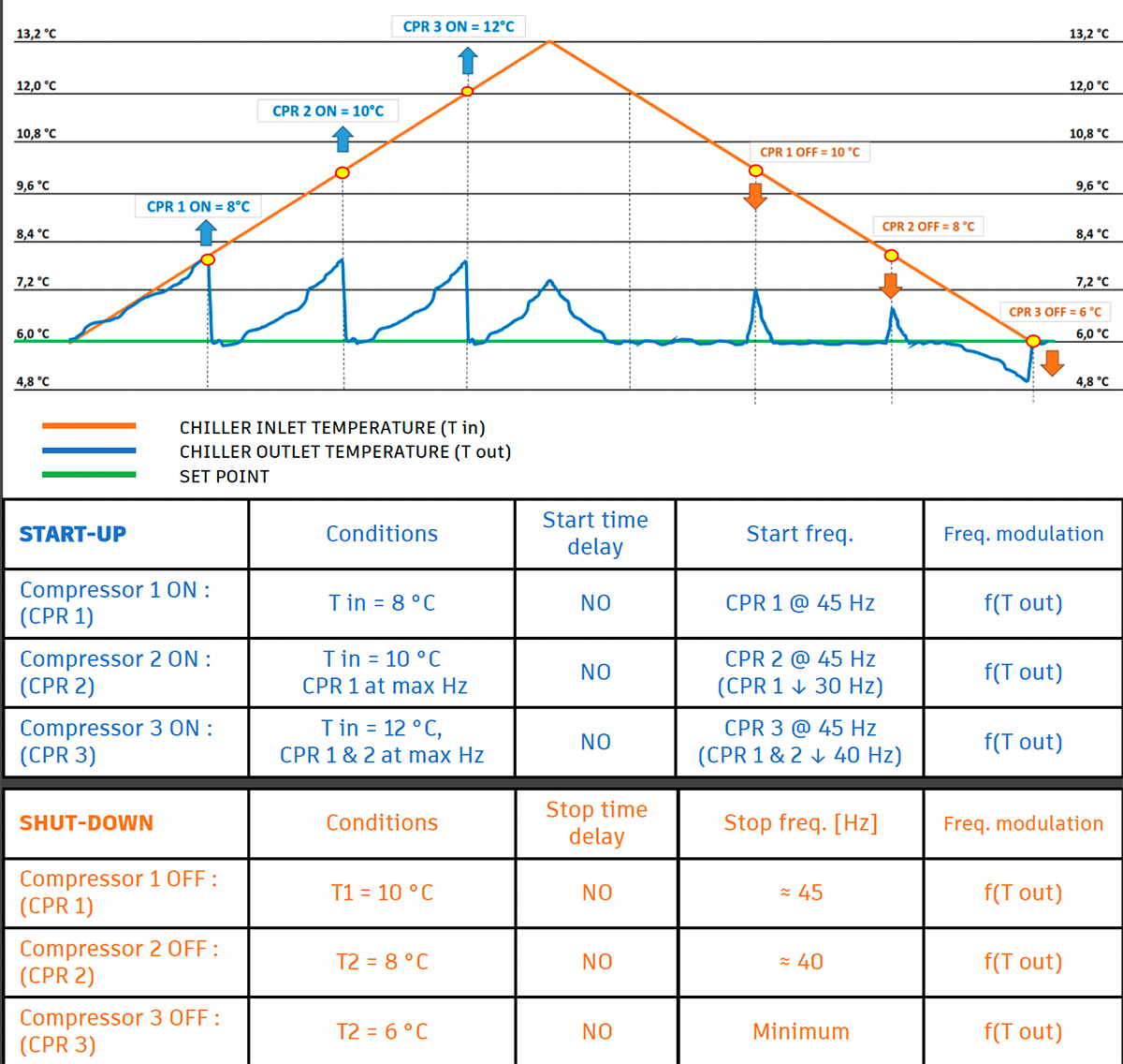
First, the start differential temperature per compressor is calculated: ΔTcpr = (ΔT / Ncpr) = 2 K. The first compressor starts when the inlet temperature is 2 K higher than setpoint. For each further increase of inlet temperature of 2 K, another compressor will start-up. When inlet temperature falls to 10 °C, indicating decrease in cooling load, the first compressor shuts down. 2nd compressor shuts-down at 8°C, and the last (3rd) compressor at setpoint value, indicating there is no cooling load.
Note: the diagram presents a specific scenario. Actual operation may differ due to different temperature regime, number of compressors etc.
6.1a BYPASS EFFECT
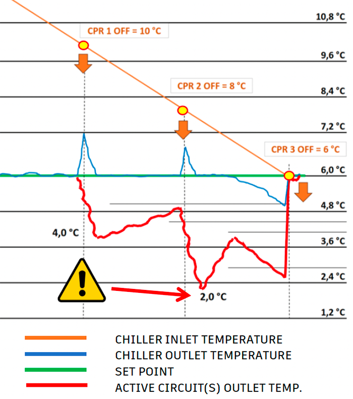
The bypass effect occurs during chiller part-load operation (when ΔT is reduced). It is especially prominent during compressor start-up and shutdown. When a compressor is turned off, its evaporator does not provide cooling anymore, so water passes through at inlet temperature. This warmer flow mixes with the cooled flow from active evaporators, increasing the supply temperature. To compensate for the mixing, active evaporators must cool the water below the set supply temperature.
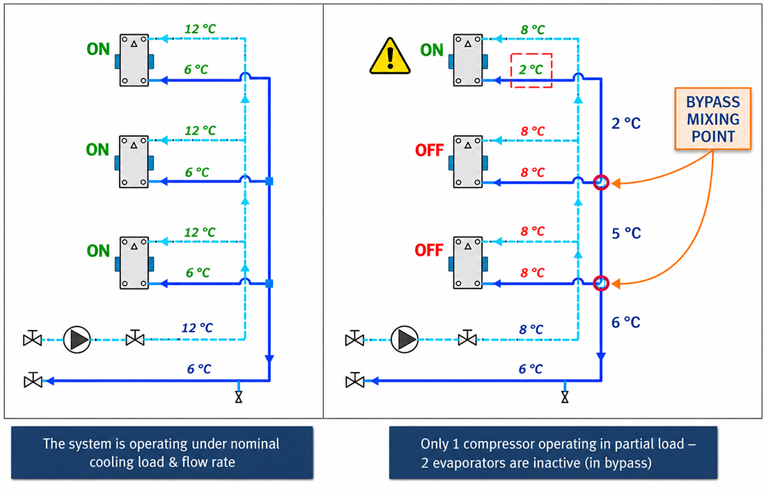
Example: For a cooling regime 12/6 °C, when 2 of 3 compressors are turned off, the remaining active circuit must cool the medium to about 2 °C (marked with the red line) to compensate for the mixing with medium from two inactive circuits.
Bypass effect can lead to freezing of coolant inside the active evaporators — especially dangerous in low-temperature systems which use water (e.g. 10/5°C and below). Especially dangerous if total flow rate is lower than nominal!
6.2 STEPPED ‘VARAIBLE’ FLOW RATE – CHILLER WITH PUMP PER CIRCUIT
This thermal regulation principle is valid for the following types of chiller / system configurations:
- Chiller with primary pump per circuit, installed in a complex hydronic system (Chapter 4.2b)
- Parallel configuration of chillers (primary pump per chiller), installed in a complex hydronic system (Chapter 4.2c)
The chiller operates with stepped ‘variable’ flow rate. The flow rate changes in discrete steps based on the number of active compressors (refrigeration circuits), while each circuit maintains a constant flow rate. Therefore, the same ΔT is maintained across all circuits without bypass during partial load.
Compressor start-up principle
The first compressor starts at a preset value below the nominal return temperature. Each subsequent compressor starts when inlet temperature reaches the same preset value above nominal common inlet temperature.
There is no starting delay regarding to inlet temperature value. However, certain starting time delays are imposed, such as minimum compressor running time at 100% of its capacity (at maximum frequency [Hz]) for a minimum period of time before any other compressor can start.
Compressor shut-down principle
The last compressor shuts down when inlet temp. reaches set point value + 0,5 × ΔT.
Each preceding compressor shuts down at a temperature differential dependent on total ΔT and number of compressors, with respect to FIFO (first-in, first-out) principle. This shut-down principle ensures balanced unloading and can be visualized on the following graph.
Note: All compressors must be equipped with frequency inverters. ON/OFF compressors are not available with this type of regulation!
The following example shows a thermal regulation diagram of a chiller with 3 independent refrigerant circuits (Ncpr = 3). Temperature regime is 12/7 °C, which means ΔT = 5 K and the cooling setpoint value is 7 °C.
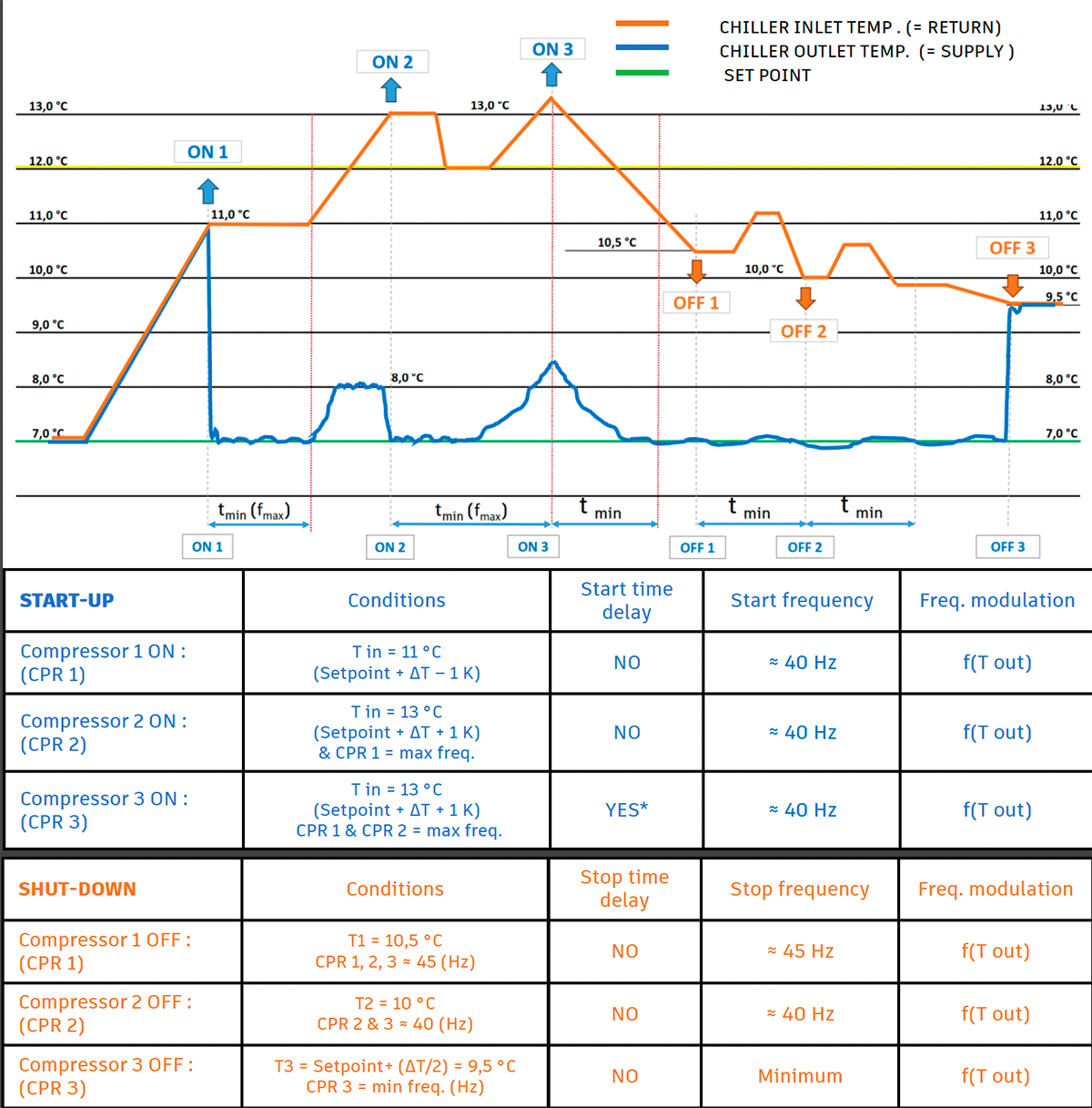
In this example, the hysteresis (dead band) is set to ±1 K relative to a return temperature of 12 °C. The first compressor is enabled solely based on the return water temperature.
Each subsequent compressor can only be enabled after the previously active compressor has reached its maximum permitted operating frequency and the minimum allowable time interval between two compressor starts has elapsed. As a result, the activation threshold for each subsequent compressor may shift to a higher return water temperature. Consequently, the third compressor is enabled at a return water temperature slightly above 13 °C. The conditions for stopping individual compressors depend on the system design parameters, including the minimum temperature difference (ΔT) required for stable compressor operation at minimum operating frequency, the minimum continuous compressor run time, and other parameters defined by the control strategy.
6.3 EMERGENCY COMPRESSOR SHUT-DOWN
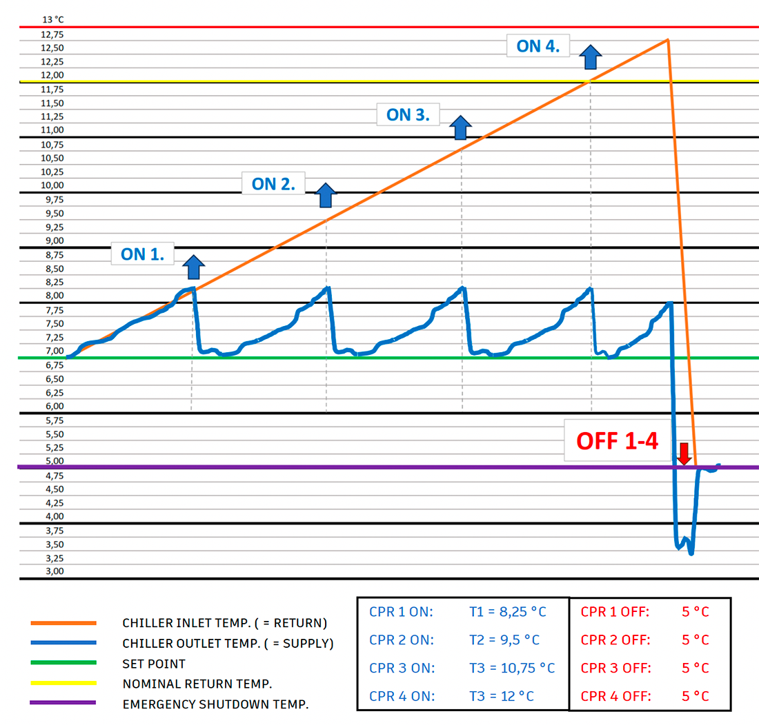
If the inlet temperature drops to 2 K below the setpoint, all compressors must shut down simultaneously. The procedure is as follows:
- Fully close the EEV
- Wait for a few seconds (predefined value)
- Shut down all compressors.
Note: Compressor frequency at shutdown can be 50 Hz or lower.
The following example diagram shows a regulation principle of a chiller with 4 independent refrigerant circuits, each circuit with one compressor. Temperature regime is 12/7 °C, which means the cooling setpoint value is 7 °C. If the chiller inlet temperature suddenly drops to 5 °C, the emergency shut down procedure is activated in order to protect the chiller.
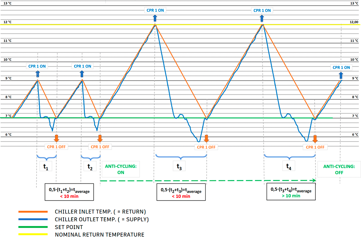
6.4 COMPRESSOR ANTI-CYCLING PROTECTION
Compressor anti-cycling protection occurs when system load is lower than minimum capacity of one compressor (i.e. refrigerant circuit).
Anti-cycling mode activates if, during the last two activations, a compressor ran on average for less than 10 minutes. Due to insufficient cooling load, the compressor operates at minimum frequency, as well in ON/OFF mode.
When anti-cycling mode is active, the controller applies an additional start differential before allowing the next start. Anti-cycling mode deactivates when the compressor operates for longer than minimum required time, which is 10 minutes. This logic ensures:
- Longer compressor runtime
- Proper oil circulation and lubrication
- Extended compressor lifespan
- Reduced wear from frequent cycling
The following diagram shows an example of anti-cycling protection. Cooling regime is 12/7 °C. The compressor start differential is 2 K above setpoint. Since the cooling load is too low, the average operating time of the first two cycles (t1 i t2) is less than 10 minutes. Therefore, the chiller controller applies additional 3 K start differential, so the total start differential equals to ΔT = 5 K. When the average operating time of the last two cycles (t3+t4) was more than 10 minutes, anti-cycling protection is deactivated.
- OVERVIEW